English
 中文简体
中文简体 русский
 Español
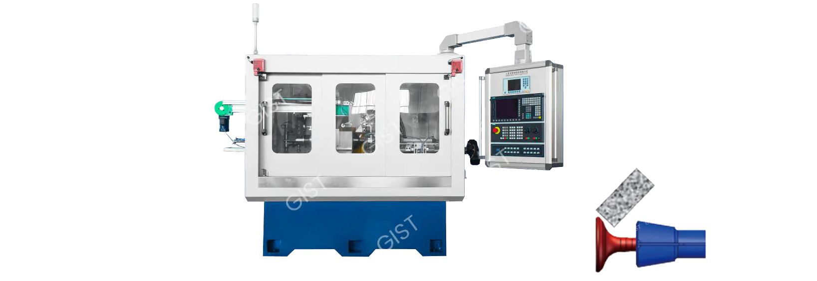
Ceramic CBN Grinding Wheel Centerless Grinding Machine
Cat:Centerless Grinding Machine
It is mainly used for precision grinding of outer circles of engine inlet and exhaust valve stems, bearings, and various shaft products.
MoreContent
The emergence of vitrified bonded cubic boron nitride (CBN) grinding wheels has provided a solution for high-precision cone grinding. CBN (cubic boron nitride) is the second-hardest material after diamond, and the vitrified bond imparts superior heat resistance and structural stability to the grinding wheel. Compared to traditional grinding wheels, the core advantages of vitrified CBN grinding wheels include:
Extremely long life: Wear resistance is over 100 times greater than that of corundum grinding wheels, significantly reducing tool changes and dressing times.
High thermal stability: Withstands temperatures exceeding 1400°C, preventing thermal deformation of the workpiece.
High precision retention: Low abrasive grain loss ensures long-term, stable machining accuracy.
High-efficiency grinding: Increases metal removal rate by 30% to 50%, significantly improving production efficiency.
Vitrified CBN grinding wheels are high-performance grinding tools made from a composite of cubic boron nitride (CBN) abrasive and a vitrified binder. This unique material combination gives them exceptional machining performance.
Properties of CBN Abrasives
Cubic boron nitride (CBN) is a synthetic superhard material with a crystal structure similar to diamond, consisting of covalently bonded boron and nitrogen atoms. CBN abrasives have the following outstanding characteristics:
(1) Extremely high hardness and wear resistance
The microhardness can reach 4500HV, second only to diamond (10000HV) and more than twice that of corundum (2000HV)
The wear resistance is more than 100 times that of ordinary corundum abrasives, making it particularly suitable for processing high-hardness materials
(2) Excellent thermal stability
High temperature resistance up to 1400°C (diamond begins to oxidize at 800°C)
Maintains cutting performance at high temperatures and does not react with iron-based metals
(3) Good chemical inertness
Does not react chemically with metals such as iron, nickel, and cobalt
Particularly suitable for processing ferrous metals such as hardened steel and high-speed steel
Characteristics of Vitrified Bond
Vitrified bond is a key factor in determining the performance of grinding wheels. Its main features include:
(1) High heat resistance
Sintering temperature can reach above 1200°C
Maintains stable mechanical properties within the working temperature range
(2) Excellent rigidity
Elastic modulus reaches above 100GPa
Small deformation during grinding, which is conducive to maintaining processing accuracy
(3) Controllable porosity
Porosity of 5%-40% can be achieved through formula adjustment
Porosity helps with chip removal and cooling, preventing workpiece burns
(4) Good self-sharpening
Abrasive grains can fall off in time after passivation, revealing a new sharp edge
Maintains continuous and stable grinding performance
Unique structure of ceramic CBN grinding wheels
Typical ceramic CBN grinding wheels adopt a multi-layer structure design:
(1) Abrasive layer
CBN concentration is usually 75%-150% (volume fraction)
Abrasive size range: coarse grinding #80-#120, fine grinding #400-#2000
(2) Transition layer
Ensures a firm bond between the abrasive layer and the substrate
Thickness is usually 1-2mm
(3) Matrix material
Aluminum alloy: lightweight, suitable for high-speed grinding
Steel matrix: high rigidity, used for heavy-load grinding
Advantages of ceramic bond
Ceramic bond is an inorganic material composed of glass phase and crystalline phase. Its advantages include:
High rigidity: more resistant to deformation than resin or metal bond, suitable for high-precision grinding
High-temperature resistance: Maintains stability even during high-speed grinding (over 120 m/s).
Excellent self-sharpening: After blunting, the abrasive grains fall away, revealing the freshly sharpened edge and maintaining sharpness.
Comparison with traditional grinding wheels (corundum, diamond, etc.)
Performance Comparison
Compared to traditional grinding wheels, ceramic CBN grinding wheels offer significant advantages:
|
Performance Specifications |
Corundum Grinding Wheel |
Resin-Resin CBN Grinding Wheel |
Vitrified CBN Grinding Wheel |
|
Maximum Operating Temperature |
800°C |
300°C |
1400°C |
|
Grinding Ratio (G-Value) |
10-50 |
200-500 |
500-2000 |
|
Maximum Linear Speed |
80m/s |
100m/s |
160m/s |
|
Dimensional Stability |
Fair |
Good |
Excellent |
|
Dressing Frequency |
High |
Medium |
Low |
Grinding Wheel Selection and Matching
Select the appropriate CBN concentration based on the workpiece material (100%-150% is recommended for hardened steel)
Grit Size Selection Principles:
Coarse Grinding: #80-#120
Semi-Fine Grinding: #150-#240
Fine Grinding: #400 and above
Binder Type Selection (Glass Phase/Microcrystalline Ceramic)
Installation Specifications
Use a dedicated flange to ensure evenly distributed clamping force
Dynamic balancing is required after installation (residual unbalance ≤ 0.4g·mm/kg)
Perform an idle run test before initial use (3 0 minutes, then gradually increase the speed to the operating speed)
Parameter Setting Key Points
Linear Speed Control:
Steel: 80-120 m/s
Carbide: 60-100 m/s
Feed Rate Selection:
Coarse Grinding: 0.01-0.03 mm/stroke
Fine Grinding: 0.002-0.01 mm/stroke
Spark Clearing Times: Perform at least three spark-free grindings during the fine grinding phase.
Coolant Management
Specialized grinding fluid (pH 8.5-9.5) must be used.
Flow Rate Requirement: ≥ 2 L/min per mm of grinding wheel width.
Filter Accuracy ≤ 25 μm. Regularly check the concentration (recommended 4 -6%)
Grinding Wheel Dressing Specifications
Dressing Tool Selection:
Coarse Dressing: Single-Point Diamond Pen
Fine Dressing: Diamond Roller
Dressing Parameters:
Dressing Feed: 0.002-0.01mm/stroke
Dressing Speed Ratio: +0.6 to +0.8 (Grinding Wheel to Roller Linear Speed Ratio)
Wear Monitoring
Regularly inspect the grinding wheel surface condition (every 8 hours)
Establish a grinding force/power monitoring system and set alarm thresholds
Record grinding wheel life data (average number of parts processed per dressing interval)
Protective Measures
A protective cover must be installed (opening angle ≤ 180°)
Operators must wear protective masks (to protect against CBN dust).
A magnetic separator must be installed in the work area to collect metal chips.
Abnormal Handling
Vibration Excess Handling Procedure:
Immediately stop the machine.
Check the spindle radial runout (should be ≤0.005mm).
Rebalance.
Workpiece Burn Response:
Check the coolant spray angle.
Reduce the feed rate by 20%-30%.
Temperature and Humidity Management
Maintain a workshop temperature of 20±2°C.
Relative humidity of 45%-65%.
Precision grinding rooms must be maintained at a constant temperature.
Vibration Prevention Measures:
Install the equipment on a vibration-resistant foundation (amplitude ≤2μm).
Avoid locating the equipment in the same area as stamping equipment.
Phenomenon: Workpiece cone angle out of tolerance (>±0.005°)
Possible Causes:
Loss of machine tool geometric accuracy (guideways/spindle)
Incorrect setting of the grinding wheel dressing angle
Insufficient workpiece/fixture rigidity causing deformation
Solutions:
Use a laser interferometer to check machine tool geometric accuracy (focusing on Z-axis and X-axis perpendicularity)
Recalibrate the grinding wheel dresser angle (using a standard angle gauge is recommended)
Add additional workpiece support points and switch to a hydraulic clamp (control the clamping force to 3-5 MPa)
Phenomenon: Roundness > 2μm
Possible causes:
Poor grinding wheel dynamic balance
Spindle bearing wear (radial runout > 0.003mm)
Excessive grinding parameters
Solution:
Rebalance the grinding wheel (target value: G1.0)
Check spindle radial runout and replace bearings if necessary (ceramic bearings are recommended)
Adjust parameters:
Reduce linear speed by 10%-15%
Reduce feed rate to 50% of original value
Phenomenon: Regular rippling patterns (wavelength 0.1-0.5mm)
Possible causes:
Grinding wheel-workpiece system vibration
Loose machine foundation
Grinding resonance
Solution:
Check and reinforce the foundation (vibration value should be ≤ 2μm/s)
Adjust the rotation speed to avoid the resonance zone (determined by FFT spectrum analysis)
Use an unequally spaced grinding wheel (such as a spiral groove type)
Symptom: Discoloration of the workpiece surface (oxidation)
Possible Causes:
Insufficient cooling (inadequate flow/pressure)
Clogged grinding wheel pores
Excessive feed rate
Solution:
Optimize the cooling system:
Increase the flow rate to 15 L/min·mm (grinding wheel width)
Use a dual nozzle design (one on top and one on the bottom, angled at 15°)
Clean the grinding wheel pores with a high-pressure air gun (0.6 MPa compressed air)
Reduce the feed rate by 30% and increase the number of polishing cycles (≥3)
Symptom: Grinding wheel life is reduced by more than 50%
Possible Causes:
Improper abrasive concentration
Changes in workpiece material (e.g., containing hard phases)
Incorrect dressing parameters
Solution:
Adjust CBN concentration:
Quenched steel: 100%-125%
Carbide: 75%-100%
Modify dressing parameters:
Reduce the dressing feed rate to 0.001 mm/stroke
Adjust the dressing speed ratio to +0.4
Phenomenon: "Bald spots" appear on the grinding wheel surface
Possible Causes:
Insufficient bond strength
Excessive impact load
Coolant corrosion
Solution:
Use high-strength microcrystalline ceramic bond
Optimize cutting method (use sloped cutting, angle <5°)
Change coolant type (avoid sulfur-containing additives)
Phenomenon: 30% decrease in metal removal rate
Possible Causes:
Grinding wheel dullness
Insufficient grinding power
Conservative process parameters
Solution:
Implement condition monitoring:
Set power threshold (85% of rated power alarm)
Use acoustic emission sensor to monitor grinding wheel condition
Phenomenon: Dimensional variation of batches > 0.005mm
Possible causes:
Accumulated thermal deformation
Measurement system error
Uncompensated grinding wheel wear
Solution:
Implement temperature compensation:
Machine warm-up time ≥ 2 hours
Install an ambient temperature control system (20 ± 1°C)
Establish an automatic compensation mechanism:
Trigger online measurement every 10 parts
Automatically correct the Z-axis coordinate via the PLC
Emergency measures:
Immediately press the emergency stop button
Check the integrity of the protective cover
Causes of investigation:
Overspeed (check the maximum speed label)
Excessive installation stress (torque the flange bolts according to the manual)
Emergency measures:
Check the clamp hydraulic pressure after shutdown (normally 3-5 MPa)
Use a secondary positioning solution (mechanical positioning + pneumatic clamping)
Add visual inspection to key processes (to confirm proper clamping)
Establish a monitoring log:
Record the grinding force curve after each dressing
Track grinding wheel life trends (control chart management)
Spare parts management:
Maintain emergency grinding wheel dressing tools (diamond rollers)
Spindle bearing spare parts (recommended mandatory replacement after 8,000 hours)
Ceramic CBN Wheel Precision Cone Grinders are high-end equipment specifically designed for machining high-precision conical parts. Their core functions are as follows:
Achieving micron-level machining accuracy (roundness ≤ 1μm, cone angle tolerance ±0.003°).
Can process a variety of conical structures:
Automotive transmission synchronizer cones
Aircraft engine mortise and tenon groove cones
Precision bearing raceway cones
Tool edge relief cones
Designed for high-hardness materials:
Hardened steel (HRC60+)
High-temperature alloys (Inconel 718, etc.)
Carbide (YG8, etc.)
Solve the problems of traditional grinding wheels being "unable to grind" and prone to burns
Integrated turning-grinding process
Complete multi-feature machining in a single clamping setup:
Cone + Cylindrical Surface
End Face + Chamfer
Profiling Surface + Groove
|
Comparison Item |
Corundum Grinding Wheel |
Vitrified CBN Grinding Wheel |
|
Dressing Life |
50 pieces |
2,000 pieces |
|
Total Service Life |
200 pieces |
50,000 pieces |
|
Dressing Frequency |
Twice per shift |
Once per week |
Surface roughness Ra reaches 0.1μm (mirror finish)
No burn layer depth <2μm (conventional grinding wheels >10μm)
Residual stress controlled within -200MPa (compressive stress state)
Significantly improved metal removal rate:
Quenched steel: 2.5mm³/mm·s (conventional process 0.8mm³/mm·s)
Carbide: 1.2mm³/mm·s (conventional process 0.3mm³/mm·s)
Cut cycle time reduced by 40%-60%
Energy Consumption Comparison:
Conventional grinder: 25kW·h/100 pieces
CBN grinder: 8kW·h/100 pieces
Waste Reduction:
Grinding chips reduced by 80%
Coolant consumption reduced by 50%
Equipped with an online measurement system (laser/contact type)
Adaptive compensation function:
Automatically corrects grinding wheel wear
Real-time compensation for thermal deformation
Digital twin system predicts machining results
Nano-ceramic bond technology:
Flexural strength increased to 180 MPa
Heat resistance increased by 30%
Multi-layer composite grinding wheel:
Base layer: High-toughness matrix
Transition layer: Gradient material
Working layer: CBN microcrystal aggregates
Cryogenic grinding technology:
Workpiece temperature <150°C (conventional process >400°C) achieved through high-pressure jet cooling
Vibration suppression technology:
Active damping system controls vibration amplitude to within 0.5 μm
Five-Axis Linkage Function:
Maximum Linkage Number of Axes: X/Y/Z/Axis/Center
Positioning Accuracy: 5μm + 5μm/300mm
Modular Design:
Quick Grinding Wheel Unit Replacement (<10 minutes)
Optional Turning/Milling Function Modules
Transmission Synchronizer Cone Machining:
Machining accuracy improved to DIN 5
Unit cost reduced by 35%
New Energy Vehicle Motor Shaft Cone Machining:
Achieve a 0.005mm fit tolerance
Eliminate the noise problem associated with traditional assembly
Engine Blade Mortise and Tenon Machining:
Fatigue life increased by 3 times
Machining cycle reduced from 8 hours to 2.5 hours
Landing Gear Bearing Cone Machining:
Surface integrity meets AMS2420 standards
Scrap rate reduced from 15% to 0.5%
Carbide Drill Back Angle Machining:
Cutting Edge Serration <3μm
Tool Life Increased by 50%
High-Precision Milling Cutters with Tapered Shanks:
Contact Area >90%
Clamping Repeatability 1μm
Intelligent Upgrades:
Integrated AI Process Optimization System
Development of a Self-Learning Grinding Wheel Condition Prediction Model
Green Manufacturing:
Dry Grinding Technology Breakthroughs
Development of Degradable Binder Materials
Ultra-Precision Machining:
Achieving Nanoscale Surface Roughness (Ra <0.05μm)
Developing Atomic-Level Removal Processes
Abnormal machining accuracy mainly manifests as excessive cone angle and poor roundness. Excessive cone angle typically refers to a deviation of more than ±0.01° between the actual machined cone angle and the design requirement, while poor roundness indicates a deviation of more than 2μm from the machined circular cross section.
For excessive cone angle, the machine tool's geometric accuracy must first be calibrated. It is recommended to use a laser interferometer to check the perpendicularity of each machine axis, particularly the perpendicularity between the X and Z axes. This test should be performed after the machine's operating temperature has stabilized, typically requiring a warm-up run of 1-2 hours. If perpendicularity deviation is detected, it should be corrected according to the machine tool manufacturer's instructions. This is generally achieved by adjusting the guide rail slat clearance to within 0.005-0.01mm.
Grinding wheel dressing is also a significant factor affecting taper angle accuracy. Diamond roller dressing is recommended, with a dressing feed rate of 0.002-0.005mm. After dressing, at least three spark-free polishing cycles are required to ensure uniformity and sharpness of the abrasive grains on the grinding wheel surface. For high-precision taper machining, it is recommended to test grind one or two workpieces before final machining. Only after satisfactory measurements are obtained can mass production commence.
Poor roundness is often closely related to the condition of the machine tool spindle. First, check the spindle radial runout, which should not exceed 0.003mm using a dial indicator. If this value is exceeded, the spindle bearings may need to be replaced. Furthermore, the grinding wheel must be dynamically balanced to G1.0 standards, with unbalance controlled within 0.4g·mm/kg. For high-speed grinding (linear speeds exceeding 80m/s), an online dynamic balancing system is recommended for real-time monitoring and adjustment.
Surface quality defects typically include chatter marks, burns, and excessive roughness. Chatter marks can be categorized as regular and random.
Regular chatter marks typically appear as uniform, periodic stripes with a wavelength between 0.1 and 0.5 mm. This type of problem is primarily caused by system vibration. Treatment measures include: precisely balancing the grinding wheel to ensure it meets G1.0 standards; adjusting the spindle speed and using FFT spectrum analysis to identify resonant frequencies to avoid sensitive speed ranges; and inspecting the machine tool foundation to ensure vibration levels are below 2 μm/s.
Random chatter marks appear as irregular surface marks, often indicating possible spindle bearing wear. Bearings should be inspected and replaced if necessary. When replacing, pay attention to the bearing preload. Excessive preload can lead to premature bearing failure.
Surface burns are primarily caused by excessive temperatures in the grinding area. Solutions include: increasing the coolant flow rate to at least 2 L/min per millimeter of grinding wheel width; checking the coolant nozzle position to ensure it is aligned with the grinding contact zone; optimizing grinding parameters, appropriately reducing the feed rate, and increasing the number of polishing cycles. For severe burns, replacing a vitrified CBN grinding wheel with one with higher thermal conductivity may be necessary.
Excessive roughness is often related to the condition of the grinding wheel. When the grinding wheel grit becomes dull, the surface roughness deteriorates significantly. Dressing the grinding wheel is necessary, and a test grind should be performed after dressing to verify the condition. If the problem persists, consider switching to a finer-grit grinding wheel or reducing the feed rate by 50%.
Grinding wheel abnormalities primarily manifest as excessive wear and abrasive grain loss. Excessive wear of a grinding wheel means its service life is significantly lower than expected, potentially reaching only 50% or even less of its normal lifespan.
Major causes of excessive wear include improper abrasive concentration, changes in workpiece material properties, and incorrect dressing parameter settings. For difficult-to-machine materials like hardened steel, it's recommended to use a grinding wheel with a CBN concentration between 100% and 125%. When machining alloys containing hard phases, the concentration can be reduced to 75% to 100%. Regarding dressing parameters, the dressing feed should be reduced to 0.001mm/stroke, and the dressing speed ratio should be adjusted to approximately +0.4.
Grit shedding manifests as localized "bald spots" on the grinding wheel surface. These localized "bald spots" are typically associated with insufficient bond strength, excessive impact loads during machining, or coolant corrosion. Solutions include: switching to a grinding wheel with a high-strength microcrystalline ceramic bond; optimizing the machining path, using a ramped entry of less than 5° to avoid impact caused by right-angle cuts; and checking the coolant composition to avoid using coolants containing corrosive additives such as sulfur.
Grinding Wheel Fracture Emergency Response
In the event of a grinding wheel fracture, the operator should immediately activate the emergency stop button to disconnect the power to the machine. Then, check the integrity of the protective cover to ensure no flying debris could injure anyone. Accident investigation should focus on: whether the grinding wheel speed exceeds the maximum speed specified on the label; whether the flange mounting flatness is within 0.01mm; and whether the grinding wheel is expired or improperly stored.
Workpiece Clamping Failure Response
Workpiece clamping failure can lead to serious safety hazards and workpiece failure. Improvement measures include adopting a dual positioning system: mechanical positioning to ensure reference position, hydraulic clamping to provide primary clamping force, and pneumatic locking as a safety feature. Visual inspection can also be added to confirm workpiece clamping is in place before processing.
Common Problem Solutions:
|
Symptom |
Possible Cause |
Solution |
|
Workpiece Surface Ripples |
Grinding Wheel Unbalance/Spindle Bearing Wear |
Rebalance/Replace Bearings |
|
Taper Angle Accuracy Exceeds |
Loss of Machine Geometric Accuracy |
Recalibrate Machine Level and Guideways |
|
Excessive Grinding Wheel Wear |
Excessive Grinding Parameters |
Reduce Linear Speed by 15%-20% |
|
Workpiece Surface Burn |
Insufficient Cooling/Grinding Wheel Dullness |
Increase Cooling Flow/Replace in Time |
|
Decreased Grinding Efficiency |
Grinding Wheel Pores Clogged |
Clear or Restore with a Special Cleaning Rod |
Daily Maintenance Key Points
Daily maintenance is essential for ensuring long-term, stable operation of the equipment. Before the start of each work shift, the following inspections must be performed: coolant concentration should be checked using a refractometer to ensure the concentration remains within the 4%-6% range; air system pressure should be checked to maintain an operating pressure of 0.5-0.7 MPa; and the grinding wheel should be visually inspected for cracks, defects, or other abnormalities.
Post-shift maintenance is equally important and includes: cleaning the workbench and magnetic separator to remove metal chips and abrasive buildup; wiping the guideway guards to prevent chips from entering the guideway surface; recording the wheel dressing data and the number of workpieces processed during the shift, and maintaining a complete equipment operation record.
Periodic Maintenance Plan
Weekly maintenance focuses on checking the guideway lubrication system to ensure that the grease level is at least 80% and that the lubrication lines are unobstructed. The hydraulic system should be thoroughly inspected monthly, focusing on the filter pressure differential. If the pressure differential exceeds 0.3 MPa, the filter must be replaced.
The spindle system should be professionally inspected quarterly, using a high-precision micrometer to measure spindle radial runout, which should not exceed 0.002 mm. The spindle temperature rise should also be checked; it should not exceed 15°C after four hours of continuous operation. Annual maintenance requires a professional technician to perform a full calibration of the machine tool and restore all positioning accuracy to factory standards.
Key Component Life Management
As a core component, spindle bearings are recommended to be replaced after 8,000 hours of operation, regardless of surface condition. Guideway sliders typically have a lifespan of five years and should be replaced promptly to avoid loss of accuracy. The grinding wheel flange should be torque-checked every 2,000 hours to ensure secure and reliable installation. Coolant should be completely replaced every three months to prevent deterioration that affects machining performance.
|
Maintenance Category |
Maintenance Item |
Operation Details and Standards |
Cycle |
Record Requirements |
|
Daily Maintenance |
Coolant Inspection |
Check concentration (4%-6%), pH (8.5-9.5), filtration accuracy ≤ 25μm |
Per Shift |
Record concentration and impurities |
|
|
Grinding wheel visual inspection |
Check for cracks, defects, and loose abrasive particles, and clean air holes (0.6MPa air gun). |
Every shift |
Take photos and archive any abnormalities. |
|
Inspect the air pressure system. |
Ensure the pressure is between 0.5-0.7MPa and that there are no leaks in the piping. |
Every shift |
Record the pressure value. |
|
|
Weekly Maintenance |
Guide Rail Lubrication |
Add special grease, fill ≥ 80% |
Weekly |
Record lubrication points and amounts |
|
|
Hydraulic System Inspection |
Check the filter pressure differential (<0.3 MPa) and the oil level within the marked range. |
Weekly |
Record the pressure differential and oil level. |
|
Grinding wheel dynamic balance check. |
Use a dynamic balancer to calibrate to G1.0 (unbalance ≤ 0.4 g·mm/kg). |
Weekly or after changing the grinding wheel. |
Record the unbalance. |
|
|
Monthly Maintenance |
Spindle Accuracy Inspection |
Measure radial runout (≤0.003mm) and axial play (≤0.002mm) |
Monthly |
Save inspection report |
|
|
Coolant Replacement |
Completely replace the coolant and clean the pipes and tank. |
Every three months |
Record the replacement date and model number. |
|
Machine tool geometric accuracy calibration. |
Check the verticality of each axis using a laser interferometer (X/Z axis ≤ 0.005mm/300mm). |
Quarterly |
Keep the calibration certificate on file. |
|
|
Annual Maintenance |
Full machine overhaul |
Includes guide rail grinding, screw preload adjustment, and electrical system insulation testing |
Yearly |
Complete maintenance report |
|
Key Component Life Management |
Spindle Bearing Replacement |
Mandatory replacement after 8,000 hours of operation, using ceramic bearings |
Accumulated by hours |
Record replacement time and batch |
|
|
Replace the guide rails and sliders |
Replace every 5 years or when significant play develops |
5 years |
Record the reason for replacement |
|
Grinding wheel flange calibration |
Check flatness (≤ 0.01mm). Bolt torque must comply with the manufacturer's instructions. |
Every 2000 hours |
Record the torque value |
|
|
Emergency Response |
Grinding Wheel Crack |
Immediately stop the machine → Check the protective cover → Check for speed/installation issues → Replace the grinding wheel |
In the event of a crack |
Fill out an incident report |
|
|
Workpiece clamping failure |
Stop machine → Check clamp pressure (3-5 MPa) → Increase visual inspection → Optimize positioning |
When this occurs |
Record corrective measures |
Maintenance Precautions:
Safety First: Before maintenance, disconnect the power supply and release the pressure. Wear protective equipment.
Tools: Use manufacturer-recommended inspection tools (such as laser interferometers and dynamic balancers).
Data Traceability: Signature confirmation is required for each maintenance operation, and the data will be archived for at least three years.
Abnormal Warning: Immediately shut down the machine for investigation if problems such as increased vibration or abnormal temperature rise are detected.
Answer:
Extremely long life: CBN's hardness is second only to diamond, and its wear resistance is over 100 times greater than that of corundum grinding wheels, significantly reducing replacement frequency.
High thermal stability: CBN can withstand temperatures up to 1400°C, preventing workpiece burns (conventional grinding wheels fail at 800°C).
High precision retention: The vitrified bond exhibits excellent rigidity, stable grinding forces, and can achieve a taper roundness of less than 1μm.
High efficiency: Metal removal rates are increased by 30%-50%, making it suitable for difficult-to-machine materials such as hardened steel and high-temperature alloys.
Grit size:
Coarse grinding (Ra 0.8μm): #80-#120
Fine grinding (Ra 0.1μm): #400-#2000
Concentration:
Hardened steel: 100%-150%
Carbide: 75%-100%
Binder:
Glass-phase ceramic: General-purpose
Microcrystalline ceramic: High toughness requirements
A: Troubleshooting steps:
Dynamic balancing: The grinding wheel must be G1.0 grade (unbalance ≤ 0.4g·mm/kg).
Check the spindle bearings: Replace if radial runout > 0.003mm.
Adjust parameters:
Reduce the linear speed by 10%-15% (e.g., from 120m/s to 100m/s).
Reduce the feed rate to 50% of the original value.
Optimize clamping: Increase workpiece support points and reduce overhang.
Answer: Common causes and solutions:
|
Cause |
Solution |
|
Excessive grinding parameters |
Reduce line speed or feed rate |
|
Insufficient coolant concentration (<4%) |
Replenish concentrate to 6% |
|
Grinding wheel pores clogged |
Clean with a 0.6 MPa high-pressure air gun |
|
Change workpiece material (contains hard phase) |
Use a higher concentration (150%) or finer grit grinding wheel |
Answer:
Cooling Optimization:
Flow rate ≥ 15 L/min·mm (grinding wheel width)
Use an internally cooled grinding wheel or a double nozzle (15° angle)
Process Adjustment:
Increase the number of polishing cycles (≥ 3 spark-free grindings)
Reduce the feed rate by 30%
Grinding Wheel Selection:
Use a grinding wheel with a high porosity (30%-40%) to enhance heat dissipation.
Answer:
Calibrating the machine's geometric accuracy:
Use a laser interferometer to check X/Z axis perpendicularity (error ≤ 0.005 mm/300 mm).
Correcting the grinding wheel dressing angle:
Use a standard angle block to calibrate the diamond roller dresser. Check fixture rigidity:
Control the clamping force at 3-5 MPa to prevent workpiece deformation.
Answer:
Dressing tool: Diamond rollers are recommended (long life and high precision).
Parameter settings:
Dressing feed rate: 0.002-0.005 mm/stroke
Dressing speed ratio: +0.4 to +0.8 (grinding wheel to roller linear speed ratio)
Grinding requirements: Three spark-free passes are required after dressing.
Answer:
Idle run test: Increase the speed stepwise to the operating speed and run for 30 minutes.
Dynamic balancing: Use an online balancer to adjust to G1.0.
Test grinding verification:
Process 2-3 specimens and inspect the dimensions and surface quality.
Finely adjust the dressing amount or grinding parameters based on the results.
Regular Chatter Marks
Characteristics: Periodic striations with a wavelength of 0.1-0.5mm
Remedy:
Check foundation vibration (should be ≤2μm/s)
Adjust speed to avoid resonant frequencies
Use an unequally spaced grinding wheel (spiral flute)
Surface Burn
Criteria: Oxygen Discoloration layer
Key countermeasures:
Increase coolant flow rate to ≥15 L/min·mm
Adopt an internally cooled grinding wheel design
Reduce feed rate by 30% and add three additional polishing passes
Abnormal wear
Typical case: Lifespan decreases by more than 50%
Optimization solution:
Adjust CBN concentration (100-125% for hardened steel)
Modify dressing parameters (feed rate ≤ 0.001 mm/stroke)
Abrasive grain shedding
Symptom: "Bald spots" appear on the grinding wheel surface
Root cause:
Bond strength Disadvantages
Right-angle cutting impact
Improvement methods:
Use a microcrystalline ceramic bond grinding wheel
Adopt a <5° slope cutting method
Dimensional instability
Key control points:
Ambient temperature control at 20±1°C
Trigger online measurement compensation every 10 pieces
Establish a thermal deformation compensation model
Grinding wheel crack
Emergency procedures:
Immediate emergency stop
Check the integrity of the protective cover
Check whether the speed exceeds the limit
Workpiece flying
Preventative measures:
Use mechanical and hydraulic dual positioning
Install a visual confirmation system
Daily Inspection:
Coolant Concentration (4-6%)
Grinding Wheel Appearance (Cracks/Defects)
Periodic Maintenance:
Weekly: Guideway Lubrication (Grease Fill ≥ 80%)
Monthly: Spindle Runout Inspection (≤ 0.003mm)
Appendix: Quick Diagnosis Table
|
Problem Description |
Priority Inspection Items |
Time Limit |
|
Chatter Marks |
Dynamic Balancing/Bearings |
Within 2 Hours |
|
Burns |
Cooling System |
Immediate Shutdown |
|
Dimensional Exceedance |
Temperature Compensation |
Resolve During Shift |
Innate advantages determined by material properties
Irreplaceable superabrasives
CBN (cubic boron nitride) boasts a hardness of 4500 HV, second only to diamond, yet its high-temperature stability (1400°C) far exceeds that of diamond (which oxidizes at 800°C).
A typical comparison: When machining hardened steel (HRC 60+), a CBN wheel's lifespan is 100 times that of a corundum wheel.
Synergistic effects of vitrified bonds: The microcrystalline ceramic structure combines rigidity (elastic modulus 100 GPa) with self-sharpening properties.
Controllable porosity (5%-40%) improves heat dissipation compared to resin/metal bonds.
A breakthrough in precision retention
Nano-level stability
Abrasive grain loss rate <0.1%/hour, ensuring the following even after 2000 cycles:
Roundness ≤ 1μm
Cone angle tolerance ±0.003°
Thermal deformation control
Thermal conductivity is 1300W/(m·K), and the grinding zone temperature is 200°C lower than that of corundum grinding wheels.
Measured data: Workpiece surface temperature <150°C when grinding titanium alloys (conventional processes >400°C)
Forward-looking technological evolution
A natural fit for intelligent grinding
Highly predictable wear behavior, suitable for:
Digital twin modeling
Adaptive control algorithm
Current leading solution: Grinding wheel remaining life prediction error <3%
Green manufacturing trends
Energy consumption comparison:
Conventional grinding: 25kW·h/100 pieces
CBN grinding: 8kW·h/100 pieces
50% reduction in coolant consumption

It is mainly used for precision grinding of outer circles of engine inlet and exhaust valve stems, bearings, and various shaft products.
More
Category: CNC lathe Product Overview: The company has passed the certification of various systems such as ISO9001:2015 quality management system, ...
More
Category: CNC lathe Product Overview: The company has passed the certification of various systems such as ISO9001:2015 quality management system, ...
More
Category: Plasma welding equipment Product Overview: The company has passed the certification of various systems such as ISO9001:2015 quality mana...
More
Category: Production auxiliary products Product Overview: The company has passed the certification of various systems such as ISO9001:2015 quality...
More
Category: Production auxiliary products Product Overview: The company has passed the certification of various systems such as ISO9001:2015 quality...
More
Category: Production auxiliary products Product Overview: The company has passed the certification of various systems such as ISO9001:2015 quality...
More
Category: Production auxiliary products Product Overview: The company has passed the certification of various systems such as ISO9001:2015 quality...
More
Category: Production auxiliary products Product Overview: The company has passed the certification of various systems such as ISO9001:2015 quality...
More
 86-13584767515
86-0515-89500828
 zhouhongwei@jiangsugist.com
 No. 1, Industrial Concentration Area, Wulie Town, Dongtai City, Jiangsu Province
Product