English
 中文简体
中文简体 русский
 Español
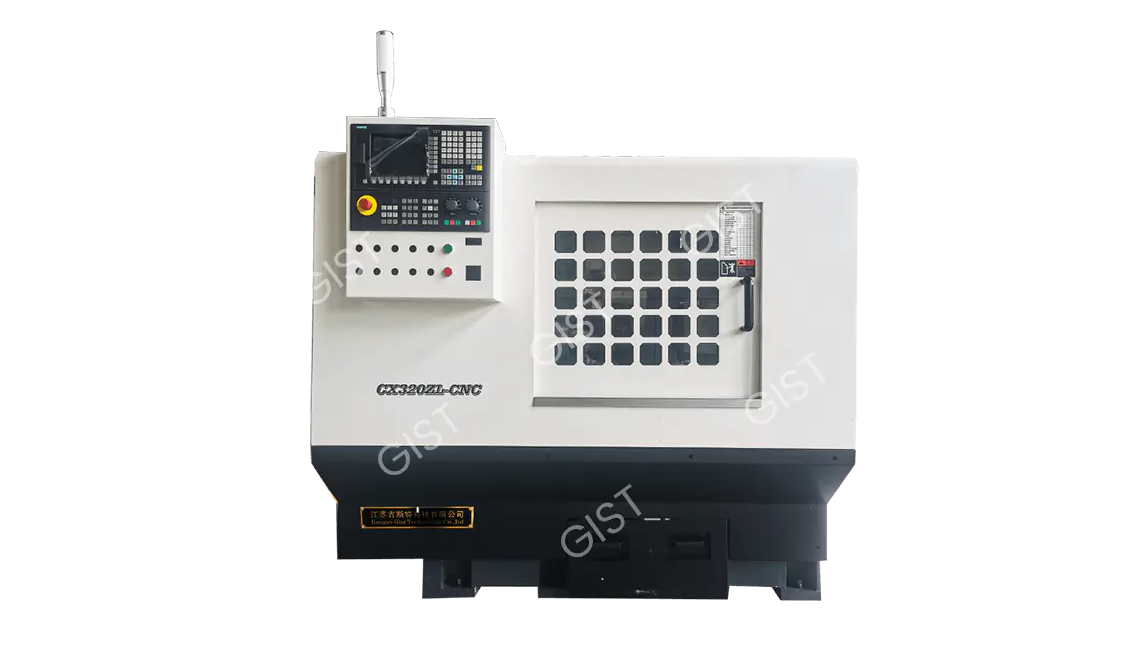
Ordinary Grinding Wheel Centerless Grinding Machine
Cat:Centerless Grinding Machine
Category: Heartless grinder Product Overview: The company has passed the certification of various systems such as ISO9001:2015 quality management ...
MoreContent
Equipment Aging and Inefficiency
Obsolete equipment with a service life exceeding 8-10 years
Efficiency loss due to wear of mechanical transmission components
Outdated control systems that fail to accurately manage energy consumption
Improper machining parameter settings
Mismatched cutting speed, feed rate, and depth of cut
Excessive idling time and low effective machining time
Continuous full-power operation of the cooling system
Inefficient motor system
General asynchronous motors have an efficiency of only 75-85%
Improper inverter parameter settings
Poor motor-load matching
Energy waste in auxiliary systems
Hydraulic system leaks and excessively high pressure settings
Excessive use of cooling and lubrication systems
Improper lighting and ventilation system design
Poor production management
Excessive idle time when equipment is idle
Unoptimized machining process routes
Lack of energy consumption monitoring and analysis systems
Equipment Upgrade and Retrofit Plan
|
Renovation Project |
Energy Savings |
Payback Period |
|
Replacement of High-Efficiency Permanent Magnet Synchronous Spindle Motor |
15-25% Energy Savings |
1.5-2 Years |
|
Installation of Intelligent Frequency Conversion Control System |
10-15% Energy Savings |
1-1.5 Years |
|
Upgrade to High-Precision Roller Guide |
5-8% Energy Savings |
2-3 Years |
|
Installation of Energy Monitoring System |
8-12% Indirect Energy Savings |
0.5-1 Year |
Processing process optimization strategy
(1) Cutting parameter optimization
Use high-speed cutting technology to improve material removal rate
Use CAM software to optimize tool path
Implement dry cutting or minimal lubrication technology
(2) Production scheduling optimization
Rationally arrange processing sequence to reduce equipment idling
Batch process similar parts to reduce tool change time
Implement preventive maintenance to avoid sudden downtime
Auxiliary system energy-saving measures
(1) Cooling system modification
Install variable frequency controlled cooling pump
Use intelligent temperature control system
Use high-efficiency coolant filter device
(2) Hydraulic system optimization
Use servo motor to drive hydraulic pump
Implement pressure matching control
Regularly check pipeline sealing
Considerations for implementing energy-saving renovations
Preliminary assessments are crucial
Conduct a detailed energy audit
Identify key energy consumption points
Calculate return on investment
Step-by-step implementation strategy
Start with the easy and then the difficult, software first, then hardware
Pioneering first, then scaling up
Establish an energy-saving baseline
Continuous monitoring and improvement
Regularly analyze energy consumption data
Establish energy-saving performance metrics
Continuously optimize processing techniques
CNC lathes (Computer Numerical Control Lathes) are modern processing equipment that uses digital signals to control machine tool motion and machining processes. They play an irreplaceable role in the manufacturing industry:
Precision Parts Machining: They are capable of precision machining various rotating parts such as shafts, discs, and sleeves, achieving dimensional accuracy of IT6-IT7 and surface roughness of Ra0.8-1.6μm.
Complex Shape Machining: Through multi-axis linkage, they can machine complex curved surfaces, tapers, threads (including multi-start threads), and special-shaped contours, shapes difficult to achieve on traditional lathes.
Mass Production Assurance: Through program control, they achieve high consistency in the machining process, making them particularly suitable for the standardized production of large-scale, high-precision parts.
Foundation for Automated Production: As a key component of flexible manufacturing systems (FMS) and automated production lines, they enable collaborative operation with other equipment.
(1) High Precision and High Repeatability
Using a ball screw drive, positioning accuracy can reach ±0.005mm.
A closed-loop control system compensates for errors in real time.
Machining repeatability reaches up to 99.9%, reducing human error.
(2) Significantly Improved Machining Efficiency
Optimized Cutting Parameters:
Spindle speed can reach over 8000 rpm (compared to 2000 rpm for traditional lathes).
Rapid traverse speed exceeds 30 m/min.
Reduced Auxiliary Time:
Automatic tool change time is 1-3 seconds.
Instant program calls are completed.
Machining efficiency is 3-5 times higher than that of ordinary lathes.
(3) Flexible Machining
Processing Different parts can be processed by changing programs.
A single machine can complete multiple processes such as turning, drilling, and tapping.
Quickly switch between product types, adapting to small-batch production of multiple varieties.
(4) Intelligent Operation
Equipped with automatic tool setting, tool compensation, and fault diagnosis functions.
A graphical programming interface simplifies operation.
Storage of hundreds of files. A single machining program can be called up at any time.
(5) Quality Controllability
Real-time monitoring of the machining process
Automatic detection and compensation of tool wear
Processing data is traceable for easy quality management
(1) Mechanical Structure
High-rigidity bed:
Made of Meehanite cast iron or resin concrete
Optimized rib structure for improved vibration resistance
Precision guide system:
Linear roller guides or sliding guides
Preloaded structure eliminates backlash
High-performance spindle:
Ceramic bearings or hydrostatic bearings
Constant temperature cooling system controls thermal deformation
(2) Control System Features
Multi-axis linkage control:
Standard configuration: X and Z axes, optional C and Y axes
Enables milling and turning operations
Intelligent function modules:
Tool life management
Adaptive control
Collision protection system
(3) Tool System Features
VDI/BMT standard turret
Supports live tools (milling and drilling functions)
Quick tool change mechanism
High-pressure cooling system (optional)
|
Comparison Items |
CNC Lathe |
Traditional Lathe |
|
Machining Accuracy |
±0.005mm |
±0.05mm |
|
Complex Parts |
Machinable |
Difficult to Machin |
|
Changeover Time |
10-30 minutes |
2-4 hours |
|
Operation Requirements |
Programming skills required |
Depends on technician experience |
|
Labor Cost |
One person can operate multiple machines |
One person operates one machine |
|
Suitable for batch production |
Single to large batch production |
Small batch production |
Typical Application Scenarios
Reduced labor dependency
One operator can manage multiple machines, reducing labor costs.
The need for skilled technicians is reduced, allowing new operators to operate with minimal training.
Material and energy savings
Optimized cutting parameters reduce scrap rates (from 5% to 0.5%).
High-efficiency electric spindles use 20% to 30% less energy than traditional motors.
Longer tool life
Intelligent cutting parameters + high-pressure coolant increase tool life by 50% to 100%.
Reduced tool change frequency reduces tool costs.
As precision machining equipment, CNC lathes are bound to encounter various problems during use. Understanding these problems and their solutions is crucial to ensuring machining quality and improving production efficiency.
Symptoms: Part dimensions after machining are outside the tolerance range
Cause Analysis:
Incorrect tool compensation parameter settings
Excessive machine backlash
Workpiece deformation during clamping
Thermal deformation caused by temperature fluctuations
Solutions:
Regularly check and compensate for backlash
Use a more stable fixture system
Control the workshop ambient temperature (preferably 20 ± 2°C)
Preheat the machine tool before machining (for at least 30 minutes)
Symptoms: Ovalization or taper on cylindrical parts
Cause Analysis:
Excessive spindle radial runout
Center and spindle misalignment
Excessive cutting forces leading to deformation
Uneven tool wear
Solutions:
Check and adjust spindle accuracy (runout should be ≤ 0.005mm)
Recalibrate center coaxiality
Optimize cutting parameters (reduce feed or depth of cut)
Replace tools regularly and implement tool wear compensation
Symptoms: Obvious tool marks or chatter marks on the machined surface
Cause Analysis:
Improper cutting parameters (too low speed or too high feed)
Improper tool geometry
Insufficient machine tool rigidity causing vibration
Inadequate cooling and lubrication
Solutions:
Increase cutting speed (150-300 m/min recommended for carbide tools)
Use a sharp rake angle and appropriate tool nose radius
Inspect and tighten all moving parts
Ensure adequate coolant flow and pressure
Symptoms: Discoloration or a hardened layer on the machined surface
Cause Analysis:
Excessive cutting temperature
Severe tool wear
Insufficient coolant concentration
Insufficient feed rate leading to increased friction
Solutions:
Replace worn tools promptly
Increase coolant concentration (5-10% recommended)
Appropriately increase feed rate (avoid less than 0.05 mm/min)
Use a high-pressure coolant system (pressure ≥ 7 MPa)
Symptoms: Spindle vibration, abnormal noise, or excessive temperature rise
Cause Analysis:
Bearing wear or poor lubrication
Uneven belt tension
Spindle dynamic imbalance
Motor drive failure
Solution:
Regularly replace spindle bearings (8,000 hours recommended)
Check and adjust belt tension
Re-balance
Check drive output current for stability
Symptoms: High movement resistance, inaccurate positioning, or abnormal noise
Cause Analysis:
Insufficient guide rail lubrication
Ineffective ball screw preload
Stuck guide rail guard
Worn guide rail surface
Solution:
Ensure the automatic lubrication system is functioning properly (oil flow rate 0.1-0.3 ml/min)
Readjust the screw preload
Clean chips from the guide rail guard
Severe wear requires replacement of the guide rail assembly
Common Alarm Codes:
Overload Alarm (AL.10)
Encoder Fault (AL.16)
Overvoltage Alarm (AL.30)
Handling Methods:
Check for excessive mechanical load
Check for loose encoder cables
Measure for stable grid voltage (380V ± 10%)
Replace servo drive if necessary
Symptom: System unresponsive or automatically restarts
Cause Analysis:
System overheating
Power supply interference
Software conflict
Insufficient memory
Solutions:
Check for proper cooling fan operation
Install a voltage regulator and filter
Regularly clear unnecessary programs
Perform system backup and restore
Wear Types:
Flank wear (replace if VB > 0.3mm)
Cradle wear
Tool tip chipping
Preventative Measures:
Select appropriate tool material (carbide/CBN/ceramic) for the material
Use optimized cutting parameters (refer to tool manufacturer recommendations)
Ensure adequate cooling and lubrication
Avoid intermittent cutting
Main causes:
Sudden changes in cutting force (e.g., uneven stock)
Excessive tool overhang
Hard spots in the workpiece
Program errors leading to collisions
Preventative measures:
Check stock stock before machining
Minimize tool overhang (no more than 4 times the diameter)
Use incremental cutting (roughing and finishing)
Use simulation software to verify the program
Common Mistakes:
Excessive clamping force leading to deformation
Improper selection of positioning datums
Failure to regularly calibrate the fixture
Correct Approach:
Use a torque wrench to control clamping force (usually 50-100 Nm)
Adhere to the principle of uniform datums
Check fixture positioning accuracy monthly (≤ 0.01 mm)
Key Maintenance Items:
Lubrication System: Check oil level and quality weekly
Cooling System: Replace coolant and clean the radiator monthly
Pneumatic System: Check the filter and drain daily
Electrical System: Check terminal tightness quarterly
Solution:
Use sharp tools (rake angle 12-15°)
Increase cutting speed (≥120 m/min)
Use cutting fluid containing extreme pressure additives
Avoid low-speed, high-feed machining
Preventative Measures:
Use PCD tools
Increase cutting speed (3000-5000 rpm)
Use kerosene-based cutting fluid
Maintain a high-quality finish on the tool rake face
When machining problems occur, it is recommended to follow these steps for troubleshooting:
Phenomenon Confirmation: Record specific symptoms (dimensions, surface, sound, etc.)
Parameter Check: Verify current cutting parameters and procedures
Tool Check: Measure tool wear
Machine Condition: Check the motion accuracy and rigidity of each axis
Process Analysis: Evaluate the rationality of the process route
Material Confirmation: Check the consistency of the workpiece material
Environmental Factors: Consider the effects of temperature, humidity, and vibration
|
Maintenance Items |
Cycle |
Inspection Details |
|
Spindle Accuracy |
Monthly |
Radial Runout, Axial Play |
|
Guide Rail Condition |
Weekly |
Lubrication Condition, Wear |
|
Turret Positioning |
Quarterly |
Repeatability |
|
Cooling System |
Monthly |
Concentration, pH Value, Flow Rate |
|
Electrical System |
Semi-Annually |
Terminal Blocks, Grounding Resistance |
Check before starting the machine
Check the hydraulic oil level (keep it at the 2/3 position of the oil window)
Confirm that the air pressure is stable within the range of 0.4-0.6MPa
Check the lubrication of the guide rails of each axis (the oil film should be evenly distributed)
Verify the coolant concentration (5-8% is recommended)
Monitoring during operation
Monitor the sound of the spindle operation (there should be no abnormal vibration and noise)
Observe the smooth movement of each axis (no creep or jitter)
Monitor the system temperature (the spindle temperature rise does not exceed 25℃)
Operation before shutting down the machine
Clean the chips on the workbench and turret (use a special brush)
Move each axis to the center of the machine tool (to avoid uneven force on the guide rails)
Check the tool wear and record it (VB value does not exceed 0.3mm)
(1) Weekly maintenance
Lubrication system maintenance
Check the oil level of the automatic lubrication pump (replenish ISO VG32 guide rail oil)
Manually lubricate the tailstock sleeve (use lithium-based grease)
Clean the inside of the guide rail guard (blow with compressed air)
Cooling system maintenance
Clean the coolant filter (mesh size ≥100 mesh)
Check the pH value of the coolant (keep it in the range of 8.5-9.5)
Remove sediment from the water tank (magnetic rod absorbs metal chips)
(2) Monthly maintenance
Inspect mechanical parts
Measure the spindle radial runout (≤0.005mm)
Check the ball screw preload (axial clearance ≤0.01mm)
Verify the turret positioning accuracy (repeat positioning ≤0.005mm)
Electrical system inspection
Tighten all connections Wire terminal (torque 2-4N·m)
Check ground resistance (≤4Ω)
Clean the electric control cabinet filter (reverse purge with compressed air)
(3) Quarterly maintenance
Hydraulic system maintenance
Replace the hydraulic oil filter (filtration accuracy 10μm)
Check the hydraulic pressure (in accordance with the equipment calibration value)
Check the pipeline sealing (no leakage)
Precision calibration
Laser interferometer to check the positioning accuracy of each axis (compensate for backlash)
Ballbar to check the roundness error (≤0.015mm)
Reset the tool compensation parameters
Spindle system
Replace the spindle bearing grease every 2000 hours (NLGI Level 2
Regularly check belt tension (deflection ≤ 10mm/100N pressure).
Keep the spindle taper clean (use a dedicated maintenance stick).
Guideway system
Check guideway scraper integrity daily.
Apply guideway anti-rust oil monthly (off-duty hours).
Adjust guideway preload every six months.
Turret system
Check tool turret locating pin wear weekly.
Clean the toolholder taper monthly (wipe with ethanol).
Lubricate the indexing mechanism quarterly (extreme pressure grease).
|
Tool Type |
Specific Item |
Application |
|
Cleaning Tool |
Nylon Brush Set |
Guideway Chip Cleaning |
|
Measuring Tool |
Dial Indicator (0.01mm) |
Spindle Runout Detection |
|
Lubrication Tool |
Manual Grease Gun |
Grease Replenishment |
Myth 1: More lubrication is better
Fact: Overlubrication will result in a thick oil film, which will reduce accuracy
Correct Practice: Lubricate according to the oil volume specified in the equipment manual (usually 0.1 ml/min)
Myth 2: Coolant only needs to be replenished, not replaced
Fact: Long-term use can breed bacteria and corrode the equipment
Correct Practice: Completely replace the coolant every three months and add biocide weekly
Myth 3: Accuracy deviation is only compensated for through software adjustments
Fact: Mechanical wear must be repaired first
Correct Practice: Repair mechanical components first, then adjust software parameters
It is recommended to establish a digital maintenance file to record the following:
Daily inspection data (temperature, pressure, abnormal conditions)
Maintenance replacement part information (brand, model, replacement date)
Accuracy test report (with test instrument model)
Troubleshooting record (symptom, cause, solution)
Control method: CNC lathes are controlled by computer programs, while conventional lathes (manual lathes) rely on manual operation.
Processing accuracy: CNC lathes can achieve accuracy of ±0.005mm, while conventional lathes generally have an accuracy of ±0.05mm.
Degree of automation: CNC lathes can automatically change tools and adjust cutting parameters, while conventional lathes require manual operation.
Application scenarios: CNC lathes are suitable for complex, high-precision, and mass production, while conventional lathes are suitable for simple parts and small-batch processing.
Mechanical wear: Wear of guide rails and leadscrews causes increased clearance.
Tool wear: Tool tip wear or chipping affects dimensional accuracy.
Thermal deformation: Thermal expansion of the machine tool or workpiece causes errors.
Programming errors: Improper code parameter settings (such as excessive feed rate).
Clamping issues: The workpiece is not clamped or is not positioned correctly.
Solution:
Regularly check and compensate for backlash.
Replace worn tools promptly.
Control the ambient temperature and preheat the machine before machining.
Optimize the machining program to ensure appropriate cutting parameters.
Possible causes:
Improper cutting parameters (such as excessive feed or low speed).
Tool overhang is too long or lacks rigidity.
Machine spindle bearings are worn or guide rails are loose.
Workpiece clamping is unstable.
Solution:
Adjust cutting parameters (increase speed, reduce feed).
Shorten tool extension (to no more than four times the tool shank diameter).
Inspect the spindle and guide rails, and replace bearings or adjust preload if necessary.
Use a more stable fixture (such as a hydraulic chuck).
Insufficient lubrication: The spindle bearings are lacking oil or the grease is aged.
Excessive load: Excessive cutting parameters (such as excessive depth of cut). Poor cooling: The spindle cooling system is faulty or heat dissipation is inadequate.
Bearing wear: Long-term use causes increased bearing clearance.
Solution:
Check the lubrication system to ensure adequate oil flow.
Optimize cutting parameters to avoid overloading.
Clean the spindle cooling channels to ensure proper heat dissipation.
If the bearing is damaged, replace it and recalibrate the spindle.
Workpiece material:
Steel: Carbide or CBN tools.
Aluminum: PCD (polycrystalline diamond) tools.
Stainless steel: Coated carbide.
Processing type:
Roughing: Use a high rake angle and strong insert.
Finishing: Use a sharp cutting edge and a small nose radius.
Tool holder type:
External turning: Use an ISO standard toolholder.
Internal machining: Use a boring tool or a dedicated internal turning tool.
Possible causes:
Excessive mechanical load (e.g., excessive cutting force).
Servo motor or drive failure.
Guide rail/lead screw stuck or poor lubrication.
Solution:
Check cutting parameters: Reduce feed rate or depth of cut.
Troubleshoot mechanical resistance:
Check guide rails and lead screw for smooth operation.
Ensure the lubrication system is functioning properly.
Electrical inspection:
Measure motor insulation resistance.
Check drive alarm codes and replace if necessary.
Optimize cutting parameters: Avoid low speeds and high feed rates; choose the right speed and feed rate.
Ensure adequate cooling: Use high-pressure coolant (especially when machining stainless steel and titanium alloys).
Check wear regularly: Replace tools if the VB value exceeds 0.3mm.
Avoid interrupted cutting: If necessary, use inserts with higher toughness (e.g., those with chipbreakers).
Daily: Clean chips and check lubrication and coolant. Weekly: Clean the guide rails and check the turret positioning accuracy.
Monthly: Check spindle runout and lead screw backlash.
Quarterly: Replace the hydraulic oil and clean the dust in the control cabinet.
Use sharp tools: Rake angle ≥ 12° and a small tool tip radius.
Increase cutting speed to ≥ 120 m/min to reduce work hardening.
Use specialized cutting fluids: Contain extreme pressure additives (such as sulfurized oil).
Avoid low-speed cutting to prevent chip sticking.
Intelligent: AI-powered optimization of machining parameters and adaptive control.
Combined: The widespread use of milling and turning and five-axis linkage technologies.
Green Manufacturing: Energy-saving motors and dry cutting technology.
Digitalization: Cloud-based monitoring and digital twin applications.
Safety Standards (Ensuring Personal and Equipment Safety)
Required: Safety glasses, noise-canceling earplugs, tight-fitting work clothes, and safety shoes.
Prohibited: Gloves (to prevent entanglement), loose clothing, jewelry, and untied long hair.
Check that lubricating oil and coolant are sufficient.
Confirm that the air pressure is stable (0.4-0.6 MPa).
Check that the chuck and turret are locked.
Keep your hands away from the machining area while the spindle is rotating.
Completely stop the machine before measuring a workpiece.
Use appropriate fixtures (such as hydraulic chucks or three-jaw chucks).
If an abnormality occurs (such as a broken tool or loose workpiece), immediately press the emergency stop button.
Regularly test the emergency stop function for proper operation. 6. Avoid Overloading
Cutting parameters (speed, feed, depth of cut) must not exceed the machine's rated values.
Overloading can easily lead to tool damage or machine failure.
Efficiency Techniques (Improving Machining Efficiency and Quality)
|
Materials |
Recommended Tools |
Cutting Speed (Vc) |
Feed (f) |
|
Ordinary Steel |
Coated Carbide |
150-250 m/min |
0.1-0.3 mm/rev |
|
Stainless Steel |
Cermet |
100-180 m/min |
0.05-0.2 mm/rev |
|
Aluminum Alloy |
PCD Tools |
500-1000 m/min |
0.2-0.5 mm/rev |
Tips:
Use high feed rates and deep cuts for roughing, and high speeds and low feed rates for finishing.
Use CAM software to optimize tool paths and reduce idle travel.
Laser/contact tool setting can quickly measure tool length and radius, improving accuracy.
Reduce human error and automatically compensate after tool changes.
Process similar parts together to reduce tool change and adjustment time.
Standardize fixtures and procedures to improve production efficiency.
Water-based coolant: Suitable for steel and stainless steel.
Oil-based coolant: Suitable for aluminum alloys and precision machining.
Minimum quantity lubrication (MQL): Reduces coolant consumption and is suitable for environmentally sensitive applications.
|
Maintenance Items |
Cycle |
Operation Details |
|
Guideway Lubrication |
Daily |
Check the oil level and clean the chips |
|
Spindle Inspection |
Weekly |
Check bearing noise and temperature rise |
|
Screw Maintenance |
Monthly |
Clean and relubricate |
Common Symptoms:
Abnormal noise during spindle rotation
Excessive spindle temperature rise (>65°C)
Excessive spindle radial runout (>0.01mm)
Possible Causes and Solutions:
Bearing wear or poor lubrication
Check lubrication system oil flow
Replace spindle bearings (factory-specified type recommended)
Appropriate amount of high-speed spindle grease
Uneven or worn belt tension
Adjust belt tension to specified value (usually 6-8mm deflection per 10kg load)
Replace worn belt (complete belt replacement recommended)
Spindle motor fault
Check motor three-phase voltage balance
Measure motor insulation resistance (should be >1MΩ)
Check encoder connection for reliability
Common Symptoms:
Abnormal noise or vibration during axial movement
Excessive positioning accuracy
Servo motor overload alarm
Diagnosis and Solution:
Ball screw wear
Check backlash (normally <0.02mm)
Adjust or replace the screw nut
Add grease (ISO 16000 is recommended) VG32 guide rail oil)
Guide rails worn or poorly lubricated
Check guide rail surface wear (use red lead powder to check contact ratio)
Clean chips from inside the guide rail guard
Adjust guide rail insert preload
Loose coupling
Check coupling tightening screw torque (refer to the equipment manual)
Replace damaged elastic coupling
Common Alarm Codes and Solutions:
|
Alarm Code |
Possible Cause |
Solution |
|
AL.10 (Overload) |
Excessive mechanical load |
Check if the guide rail/lead screw is stuck |
|
AL.16 (Encoder) |
Encoder cable faulty |
Check connectors and replace damaged cables |
|
AL.30 (Overvoltage) |
Grid voltage fluctuation |
Install a voltage regulator |
|
AL.31 (Undervoltage) |
Power module faulty |
Check if the input voltage is normal |
Common Problems and Solutions:
System freeze or black screen
Check the power module output voltage (usually +5V, ±15V)
Clean the system cooling fan
Back up the system parameters and reinstall the system
Program execution errors
Check G-code syntax errors
Verify tool compensation parameter settings
Check if the memory is full
Communication failure
Check the RS232/USB interface connection
Restart the communication protocol
Update the driver
Common Problems:
Unstable pressure
Sluggish cylinder movement
Excessive hydraulic oil temperature
Solutions:
Check the hydraulic oil level and quality
Refill to the centerline of the oil gauge
Replace cloudy or emulsified hydraulic oil (recommended every 2000 hours)
Clean or replace the filter element
Check for filter blockage
Replace the precision filter element (filtration accuracy ≤10μm)
Check the oil pump and solenoid valve
Test the oil pump output pressure
Clean a stuck solenoid valve spool
Common Problems:
Insufficient air pressure
Improper cylinder movement
Air leakage
Solution:
Check air supply pressure (should be ≥0.5 MPa)
Clean or replace clogged filters
Replace damaged air pipe fittings
Lubricate the cylinder (use dedicated pneumatic lubricant)
Common Problems:
Insufficient coolant flow
Clogged nozzles
Coolant pump inoperative
Solutions:
Check coolant tank level
Clean filters and nozzles
Check coolant pump motor operation
Adjust coolant concentration (5-8% recommended)
Common Problems:
Poor guide rail lubrication
Clogged lubricant oil line
Lubricant pump inoperative
Solution:
Check lubricant tank level
Clean distributor blockages
Adjust lubrication interval (usually every 15-30 minutes)
Replace failed lubrication pump
Common Types and Causes:
Excessive Flank Wear
Excessive Cutting Speed
Uneven Workpiece Hardness
Cradle Wear
Excessive Feed Rate
Insufficient Cooling
Cutter Tip Chipping
Intermittent Cutting
Excessive Tool Overhang
Solutions:
Optimize Cutting Parameters
Improve Cooling Methods
Select a More Suitable Tool Material
Common Problems:
Tool Magazine Not Rotating to Position
Tool Changer Robot Stuck
Tool Identification Error
Solutions:
Check Tool Magazine Origin
Clean Tool Holder Taper
Adjust Robot Air Pressure
Check Tool Identification Sensor
Daily Maintenance:
Clean chips and coolant
Check hydraulic/pneumatic systems
Verify axis zero return accuracy
Weekly Maintenance:
Check guideway lubrication
Clean electrical control cabinet filters
Backup system parameters
Monthly Maintenance:
Check spindle runout
Check ball screw wear
Calibrate automatic tool setter
Quarterly Maintenance:
Replace hydraulic oil and filter
Check ground resistance
Full accuracy check
High-Precision Machining: Dimensional accuracy reaches IT6 (0.002-0.004mm)
Complex Shape Processing: Capable of producing complex geometric shapes such as threads, tapers, and curved surfaces
Stable Mass Production: Program-Controlled Processing Ensures Product Consistency
High Level of Automation: Supports automatic tool change, automatic measurement, and other functions
Flexible Production: Rapidly Switch Between Processing Types
Typical Parts:
Engine Components: Crankshafts, camshafts, connecting rods
Transmission Systems: Transmission gear shafts, differential housings
Braking Systems: Brake discs, brake drums
Steering Systems: Steering knuckles, steering shafts
Specific Applications:
Ensuring part interchangeability during mass production
Precision turning of high-hardness materials (such as hardened steel)
One-step forming of complex contours
Combined with robots for automated production lines
Typical Parts:
Engine Parts: Turbine Shafts, Compressor Discs
Landing Gear Components: Actuators, Connecting Shafts
Spacecraft Structural Parts: Docking Flanges, Fuel Nozzles
Special Requirements:
Processing of Difficult-to-Machining Materials Such as Titanium and High-Temperature Alloys
Strict Geometric and Positional Tolerances (Roundness ≤ 0.005mm)
Surface Integrity Control (No Hardened Layer)
Solution:
Use of a High-Pressure Cooling System (Up to 7MPa)
Use of CBN Tools for Hard Turning
Equipped with an Online Measurement System for Real-Time Compensation
Typical Products:
Orthopedic Implants: Artificial Joints, Bone Screws
Dental Instruments: Implants, Prostheses
Surgical Instruments: Endoscope Components, Surgical Handles
Special Processes:
Processing of Biocompatible Materials (Titanium Alloy, Cobalt-Chromium-Molybdenum)
Mirror-Grade Surface Roughness (Ra ≤ 0.2μm)
Processing of Micro-Precision Parts (Minimum Diameter 0.3mm)
Technical Solution:
Air Spindle (50,000 rpm)
Minimum Quantity Lubrication (MQL)
High-Precision Optical Tool Setter
Typical Applications:
Injection Molds: Cores, Cavities
Die-Casting Molds: Cores, Slides
Stamping Molds: Guide Pins, Bushings
Processing Features:
Processing of High-Hardness Mold Steel (HRC 50-62)
Complex Curved Surface Forming
High Surface Quality Requirements
Process Innovations:
Mill-Turn Combination Machining Instead of EDM
Use of Spherical Turning Tools for Surface Finishing
Laser Measurement for Online Inspection
Typical Parts:
Fiber Optic Connectors: Ceramic Ferrules
RF Devices: Waveguide Cavities
Semiconductor Equipment: Vacuum Chambers
Precision Requirements:
Dimensional Accuracy: ±0.001mm
Surface Roughness: Ra: 0.1μm
Geometric Tolerance: 0.002mm
Solution:
Constant Temperature Workshop Environment Control (20±0.5°C)
Natural Diamond Tool Finishing
Active Vibration Isolation System Application
Application Scenarios:
Multiple processes such as turning, milling, and drilling must be completed in a single setup;
Processing of complex and irregularly shaped parts;
High-precision positioning requirements
Typical Case:
Machining of aircraft engine blisks, achieving precise shaping of the blade profile through B-axis linkage.
Applications:
Large-batch production of small precision parts; Continuous bar stock processing; Production of standard automotive parts
Production Efficiency:
A 6-spindle CNC lathe can process bolts with a daily output of up to 15,000 pieces.
Applicable Parts:
Large disc-shaped parts; Heavy rotating bodies; Asymmetrical and complex parts
Processing Advantages:
Easy workpiece loading and unloading; Gravity facilitates chip removal; Suitable for large-diameter parts
Intelligent Machining:
Adaptive Control Systems
Automatic Tool Wear Compensation
Machining Quality Prediction
Green Manufacturing:
Dry Cutting Technology
Energy-Saving Electric Spindle
Waste Recovery
Ultra-Precision Machining:
Nanoscale Surface Machining
Atomic-Level Dimensional Control
Quantum Device Manufacturing
Remote Monitoring:
Cloud-Based Data Management
Remote Fault Diagnosis
Cross-Factory Collaborative Production
When selecting a CNC lathe based on the application, consider the following:
Accuracy Level:
General Machining: ±0.01mm
Precision Machining: ±0.005mm
Ultra-Precision Machining: ±0.001mm
Spindle Configuration:
Conventional Machining: 8000rpm
High-Speed Cutting: 15000rpm
Micro Parts: 40000rpm and above
Automation Requirements:
Single-Machine Production: Manual Loading and Unloading
Mass Production: Robot Integration
Flexible Manufacturing: AGV Connection
Turret Type Selection
Servo Turret: Tool change time 0.3-0.8 seconds (preferred for mass production)
Hydraulic Turret: Low price but complex maintenance (selectable for budget-constrained applications)
Power Turret: Essential for milling and turning (B-axis linkage)
Tool Interface Standards
VDI System: German standard, excellent rigidity
BMT System: Japanese standard, fast tool change
CAPTO Interface: High-end configuration, high precision
Automation Level Selection Guide
Basic Model
Manual Loading/Unloading
Standalone Operation
Suitable for: Trial Production/Small Batch
Standard Model
Robot Loading/Unloading
Automatic Door Opener
Suitable for: Medium Batch (500-2000 pieces per month)
Intelligent Model
AGV Logistics System
Online Inspection and Feedback
Suitable for: Large Batch (5000+ pieces per month)

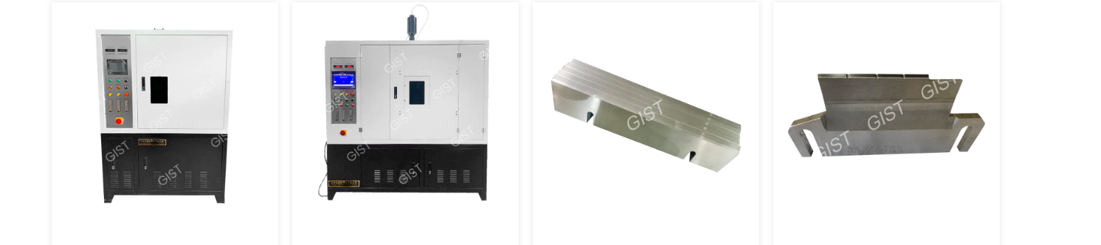
Category: Heartless grinder Product Overview: The company has passed the certification of various systems such as ISO9001:2015 quality management ...
More
Category: CNC lathe Product Overview: The company has passed the certification of various systems such as ISO9001:2015 quality management system, ...
More
Category: Special valve CNC grinder Product Overview: The company has passed the certification of various systems such as ISO9001:2015 quality man...
More
Category: Heat treatment equipment Product Overview: The company has passed the certification of various systems such as ISO9001:2015 quality mana...
More
Category: Production auxiliary products Product Overview: The company has passed the certification of various systems such as ISO9001:2015 quality...
More
Category: Production auxiliary products Product Overview: The company has passed the certification of various systems such as ISO9001:2015 quality...
More
Category: Production auxiliary products Product Overview: The company has passed the certification of various systems such as ISO9001:2015 quality...
More
Category: Production auxiliary products Product Overview: The company has passed the certification of various systems such as ISO9001:2015 quality...
More
 86-13584767515
86-0515-89500828
 zhouhongwei@jiangsugist.com
 No. 1, Industrial Concentration Area, Wulie Town, Dongtai City, Jiangsu Province
Product